Disclaimer
Please exercise safety when building pedals. While the voltages being worked with are small, be mindful of electrocution. Wear proper safety gear, take breaks, and solder in a well-ventilated room. I don’t offer any sort of technical assistance and these build logs are meant for educational purposes only. Proceed with caution.
Also, I am not associated with any of the companies or groups/people mentioned in this post. I patronized their businesses and entities so I would like to share/promote them.
Background
For a while, I avoided making any sort of germanium transistor-based pedals because of a series of errors while building some Hudson Broadcast clones. However, I became enamored with revisiting the idea after hearing demos of a fuzz by a local builder, LST Gnome Electronics. Germanium fuzzes consisting of 1-2 transistors may seem simple, but they are like making cacio e pepe: Small quantity of ingredients but require the right execution to get working.
Looking to bypass the steps of germanium transistor selection, I opted for matched transistors from Amplified Parts. From there, I wanted to really mimic the look of vintage fuzzes from the UK, and purchased a slanted fuzz case, large potentiometers, and axial capacitors to mimic that old school look. Also, having forgotten to source 22uF radial capacitors from Amplified Parts, I defaulted to using eBay. (Although during a chance trip to LA, I did come across an electronics store that sold “mojo parts” including radial 22uF capacitors.)
I implemented a couple ideas like the Incandeza Bypass by Demedash Effects relay bypass, SMD components, and a voltage inverter to provide a -9V power supply. I did have plans to insert a pick-up simulator and temperature controls as adapted from the Benson Germanium Fuzz, but the idea proved to be overly ambitious. Furthermore, the slanted structure of the fuzz case I was working with was difficult to design a PCB around.
Making a Stripboard Version
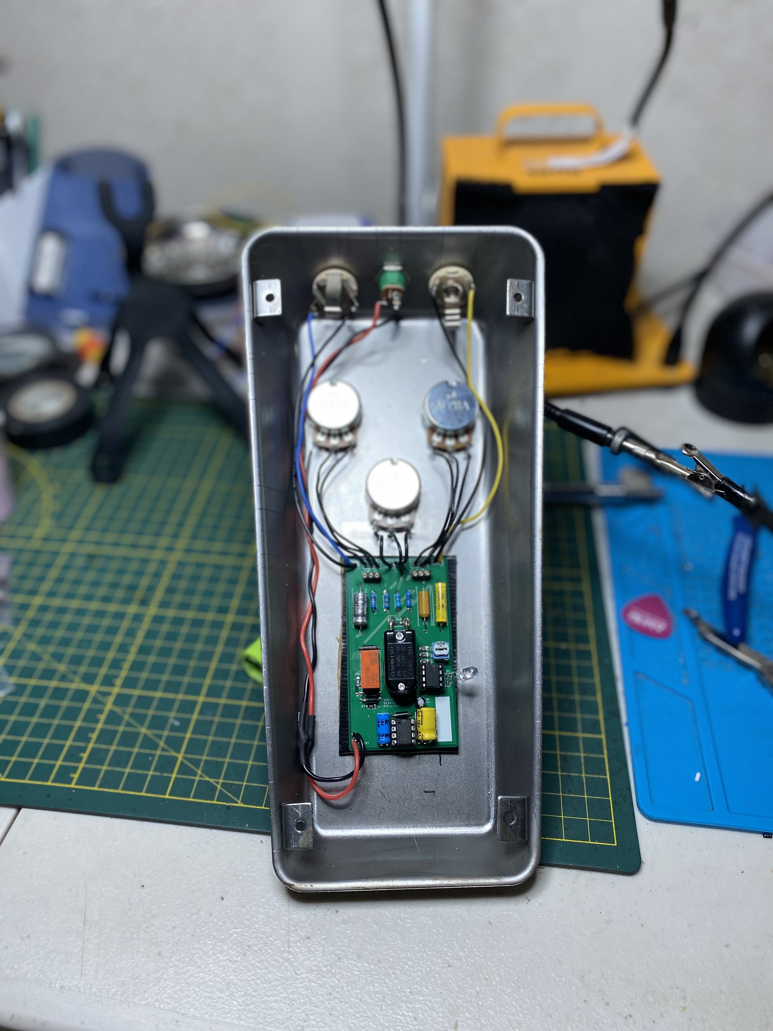
This version features stripboard. The insides are not pretty, and I did have to heavily pad the enclosure because the components/joints kept making contact with the case.
As you’ll read in the following section, I did have plans to make a PCB. While waiting for the PCBs to be delivered, I did make a stripboard version of the pedal. Because the transistor set includes specific values for the resistors, I did have to copy those resistor values by soldering together resistors of differing values. This worked but did not lead to pretty results, and because of the compact stripboard layout for the fuzz portion of the circuit (the charge pump is on a different piece of stripbroad), the resistors had a tendency to touch the germanium transistors, short circuiting the pedal in the process.
Creating a PCB
I used the provided Fuzz Face schematic from Amplified Parts in combination with the Sun Face schematic from PedalPCB. I wanted to go with something that was mountable to the footswitch, and I was going be using lugged potentiometers. Later I would find that the pre-drilled holes on the fuzz case were more fitting for the smaller Alpha potentiometers. Using the larger potentiometers did require me to expand the holes in the case. The metal used for the case is incredibly strong - almost to a fault, and I found that expanding these holes as well as adding an additional hole for a DC jack was quite difficult.
The PCB design as done on EagleCAD. Note the wavy traces - they are meant to mimic vintage fuzz circuit boards. To be clear, this is NOT an optimal way to do traces and only serve an aesthetic purpose.
I did make some changes to the original fuzz face schematic by implementing the popular Bias knob mod. I also put in the original resistor (R9 in the schematic below), which can be used if a person opts against the Bias knob. Furthermore, I implemented jumper pads into the PCB to allow for a silicon version, based on the Analog Man Silicon Sun Face, to be built. Also, the board size allows this pedal to be build into a 1590B enclosure; however, this will require smaller solder-lug potentiometers. If anyone wants to bias their transistors, I recommend substituting R7 and R9 with these boards.
Gutshots
Axial capacitors are used for the actual fuzz circuit. The footprints allow for a full 18mm long component with 5-8mm width. They offer no sonic advantage. They just look cool.
Completed board sans germanium transistors. The footswitch holds the PCB against the enclosure. There is a piece of cardboard between the PCB and the enclosure to prevent the joints of the circuit from shorting against the enclosure. I lifted this idea from Effects Layouts’ Incandenza Bypass layout.
Socketed transistors. There is a LED inside the enclosure. I was going to omit it all together but I needed it while testing to ensure power is going to the circuit.
Completed pedal. The PCB version had way less squealing than the stripboard version.
Schematic
Schematic of the final design. The Test pad is a suggestion by Demedash to check for any power spikes. Note the jumpers. Pad 1 and Pad 2 are an error when I thought I could sub in a LT1054. C3, C4, and C5 appear as resistors in the schematic because I couldn’t find axial capacitor footprints for the PCB.
Parts
If you wish to build a similar pedal, here are the parts I sourced from Amplified Parts:
Germanium transistor set. I used a T7-H, which is somewhat questionable for testing germanium transistors. I got an hfe of 50-60 and 70-80 for Q1 and Q2 respectively. I did not test for leakage.
Axial capacitors: Non-polarized, polarized.
Additional parts like the relay, footswitch, DC jack, audio jacks, and radial capacitors, ICs were sourced from Electronics Warehouse in Riverside County (CA), Jameco, and Love My Switches.


